Background
After buying my first mechanical keyboard and understanding what makes them so unique, I wanted a mechanical keyboard for my desk at work. Given the simplicity of mechanical keyboards, in terms of the components and how they function together, I set out to design my own keyboard because I believed that I had the skills to design the majority of the components.
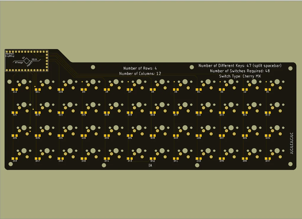
Most microcontrollers have less than 20 GPIO (general purpose input/output) pins, therefore depending on the microcontroller that was used, there would be a limit to the size of the keyboard’s matrix. Staying true to the theme of trying new things, I decided to go with an ortholinear design. This means that in addition to all of the rows being aligned like in most other keyboards, the columns are also aligned. Given that this design for a keyboard already exists on the market, I was determined to finish the project and see the final BOM (bill of materials) to do a comparison with a very popular ortholinear keyboard already on the market.
The PCB
One of the main reasons that I decided to design the PCB (printed circuit board) for this keyboard is because I have been designing a lot of PCBs at work and I was up for the challenge to design something new. Designing the PCB meant that I would have the dimensions of the PCB, the location of the microcontroller, and the location of the mounting holes. All of these would work to my benefit when designing the case for the keyboard.
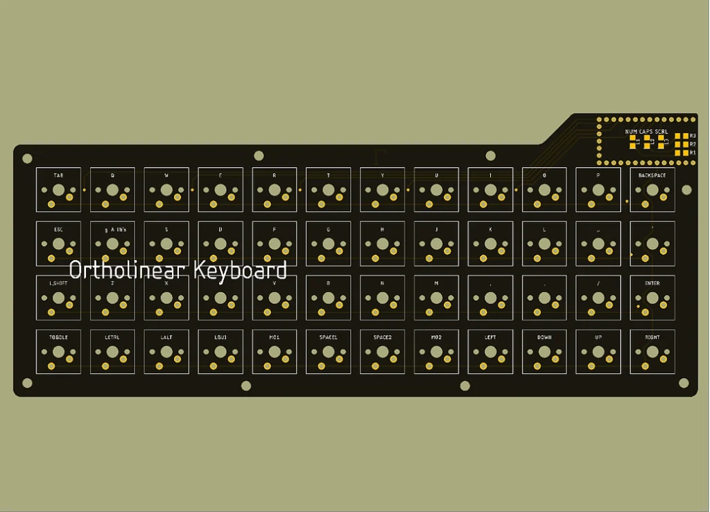
I designed the PCB to work with an Adafruit ItsyBitsy 32u4 5V module because it would simplify the assembly of the PCB for others. There are two different types of footprints (placement on a PCB for a component) for key switches- one with PCB mounting pegs, one without PCB mounting pegs. I chose to go with mounting pegs due to its versatility and the added support that it would give my overall design.
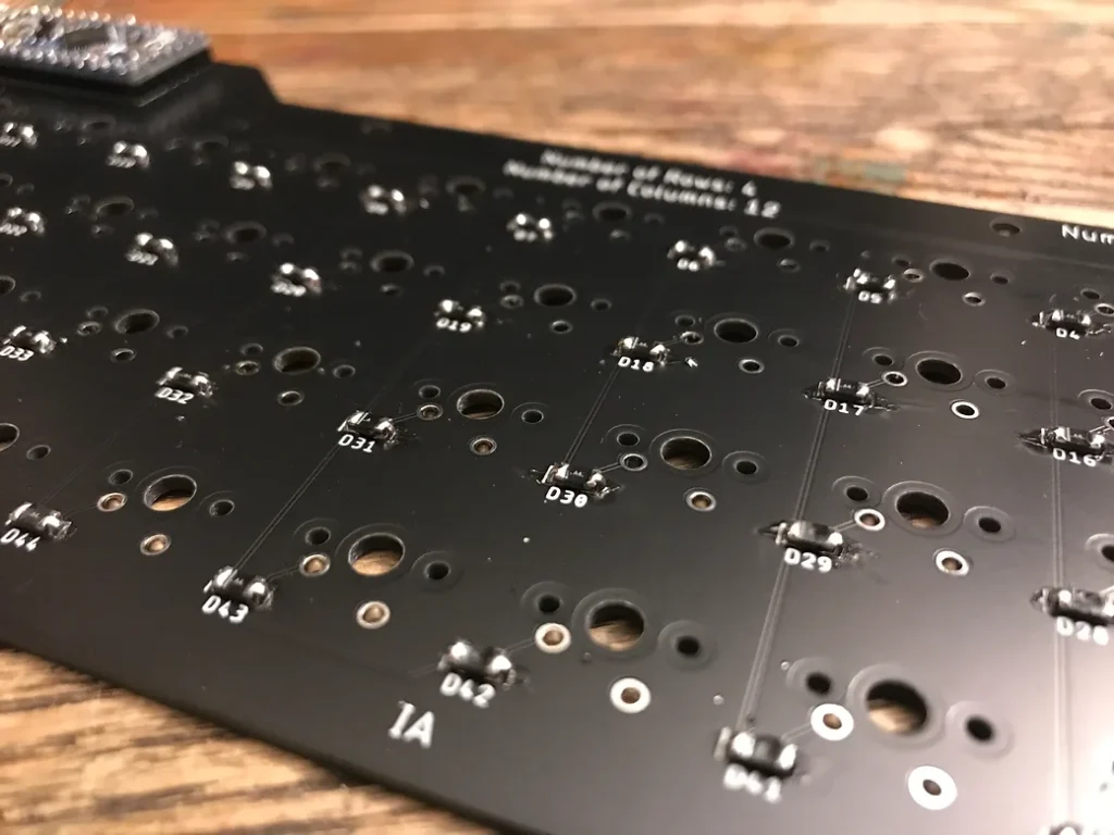
If multiple keys are pressed at once on a keyboard, a phenomenon known as ghosting may occur. Ghosting is when a signal sent to the connected device is for a key that was never pressed; as if a ghost pressed a key. Each switch requires a diode so that signals are properly transmitted to prevent ghosting. If you scroll through the images below, you will see 1206 Schottky diodes on the backside of the PCB for each individual switch.
In addition, I added some SMD LEDs and respective current limiting resistors for Num Lock, Caps Lock, and Scroll Lock indicators. Num Lock does not apply to this keyboard but I have the option of changing its function in the future.
The Case
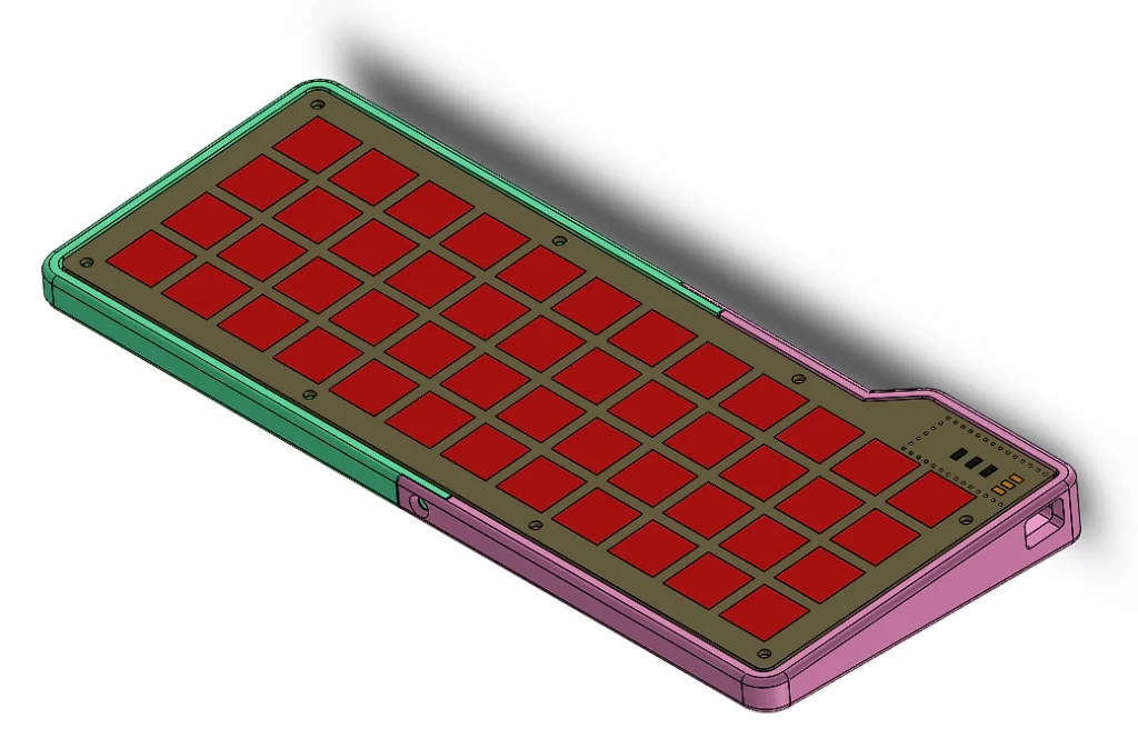
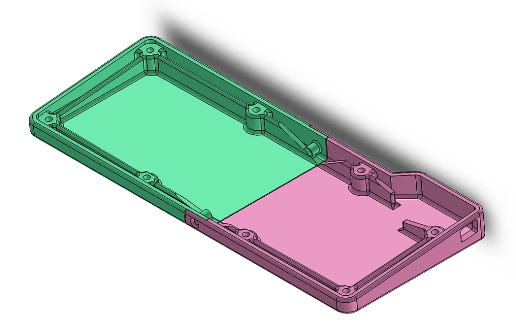
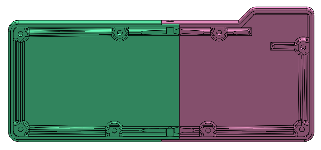
Because I have an FDM 3D printer at home, I decided to design a case that I could print out of PLA (polylactic acid is one of the most commonly used thermoplastics for 3D printing). This method of designing has its benefits. 3D printing would allow me to rapidly produce cases for this keyboard in the event that I need to adjust any tolerances. Tapping screws directly into PLA isn’t reliable because over time the threads in the plastic will wear out. Instead, I used M3 threaded heat-set inserts for my screws. Using heat-set inserts is a great way to add machine threads to a printed part so that one could attach printed parts together or non-printed parts to printed parts. Brass is stronger than most printed plastics after all.
Given the length of the keyboard, I had to go with a two-piece design so that I could fit the two halves into my 3D printer. Channels were created in each half so that the left half would rest on top of the right half and screws from the outside of the case would hold the two pieces together. When the PCB is screwed into the case, there would be added rigidity between the two halves of the case. I will admit this isn’t a perfect way of holding everything together, but for a keyboard, something that will sit stationary without any torsional forces for the entirety of its lifetime, it is good enough. The beautiful part of this project is that in the future I can redesign a better, stronger, case and just swap it.
The Switches
There are three main types of switches:
- Linear: linear switches require a linear amount of force to press down fully before bottoming out. There are no tactile bumps on the way down, the keypress is smooth with zero feedback from the key switch
- Tactile: tactile switches are like linear switches except there is a tactile bump at the actuation point (the point at which the switch is activated). The tactile bump gives the user sensory feedback of when the switch is activated
- Clicky: clicky switches are like tactile switches except instead of a tactile feeling that is somewhat audible, a clicky switch can definitely be heard. Think of the clicky feeling and sound of clicking a mouse. The different ways that a clicking sound is made is a whole different can of worms.
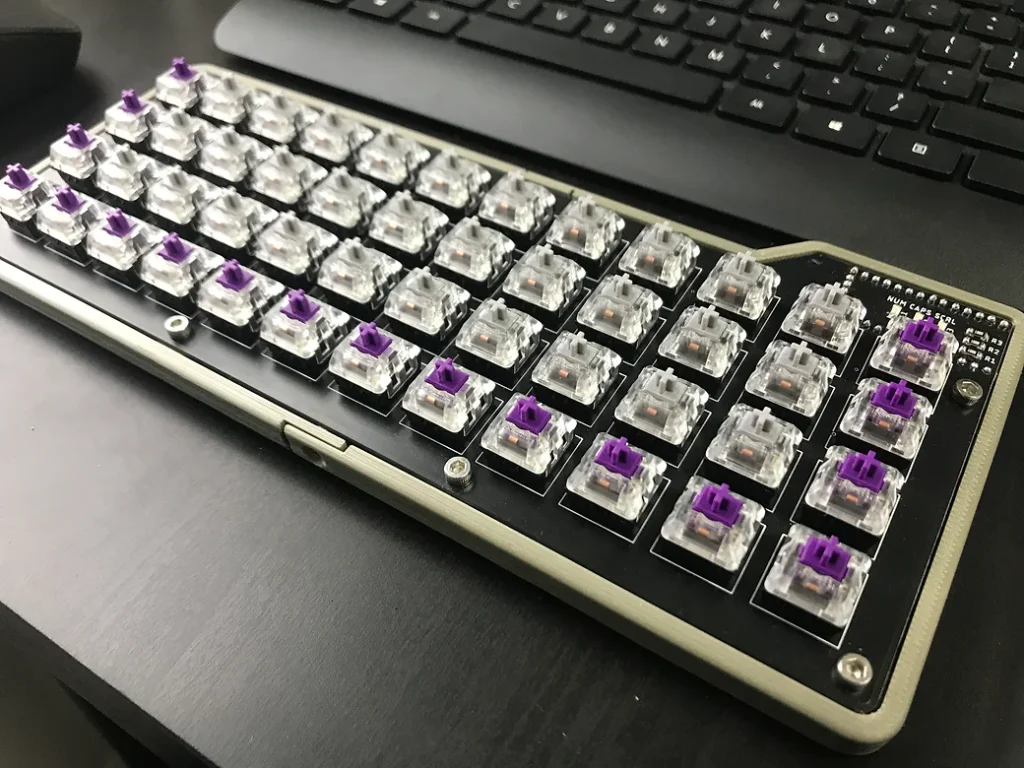
Tactile switches are my prefered switches to type on, but they can be loud and distracting to some. Given that this keyboard was going to be used at the office, where there would be people around me, I decided to use linear switches (Kailh Speed Silvers) for the main switches and tactile switches (Kailh Pro Purples) for the less commonly used switches. I had to include some tactile switches for my sanity.